 1 of 3
The industries that define our lives including healthcare, transportation, finance, retail, manufacturing and many others are rapidly changing. It’s inspirational, motivating and unstoppable.
Get white paper In partnership with%20(1).png)
An explanatory overview of the features and functions of an intent-based software-defined campus LAN, simplifying the differences between traditional networking and SDN (Software Defined Networking).

Download our White Paper to gain insight into the features and functions of Intent Based Campus Fabrics with Software Defined Access.
Following on from an article that we wrote regarding the differences between Catalyst IOS and NX-OS, this is the first in a series that seeks to simplify the differences between traditional networking and SDN (software defined networking).
The first and most significant difference is automation and orchestration. Traditionally a LAN implementation, for example, would require low-level configuration of each and every device that comprises the LAN, which can be a laborious process, and it also means that any subsequent changes need to be made to each device. With SD-Access, network configuration is automatic and based upon a single policy that governs how the network will behave. Changes and additions are also automatic, with the changes to the policy being passed down to the devices by a controller.
Another important point is that SD-Access unifies both wired and wireless access together, whereby the same policies are propagated to both wired and wireless access networks at the same time.
A network policy controller (3rd party provisioning tools notwithstanding) is not a brand new concept in networking; however, the way that it’s implemented for Cisco SD-Access is. The main principles of SD-Access operation are as follows:
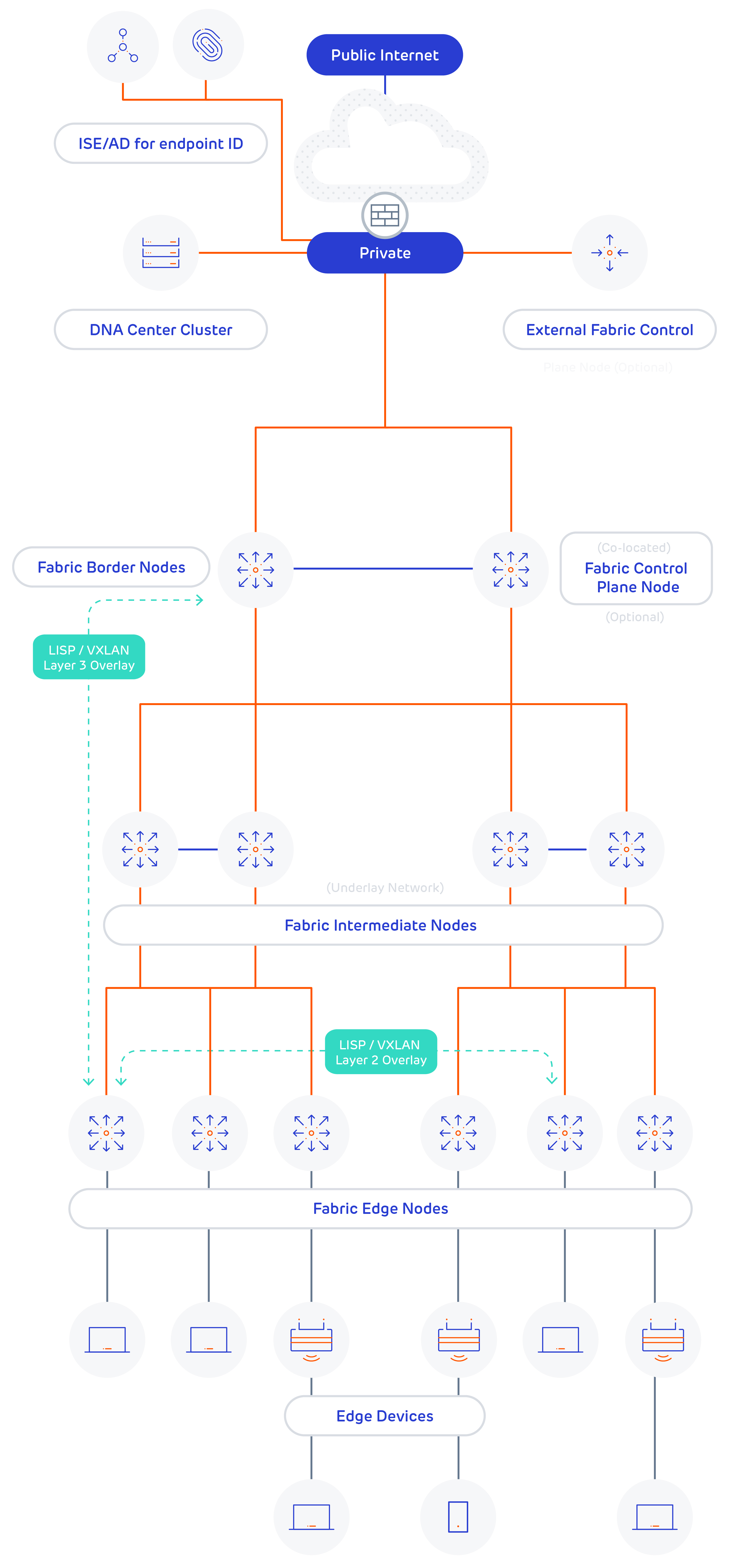
A diagram detailing the components of SD-Access is shown below, the main points to note are:

Download our White Paper to gain insight into the features and functions of Intent Based Campus Fabrics with Software Defined Access.
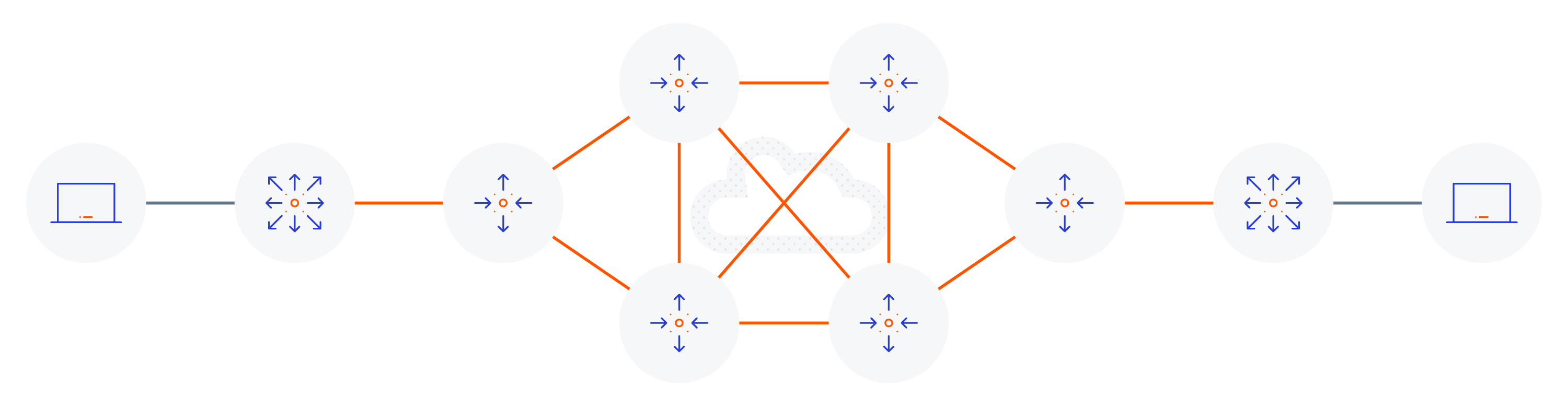
If we consider a typical (non SD-Access) topology from an endpoint perspective, a physical topology would look something like the following diagram.
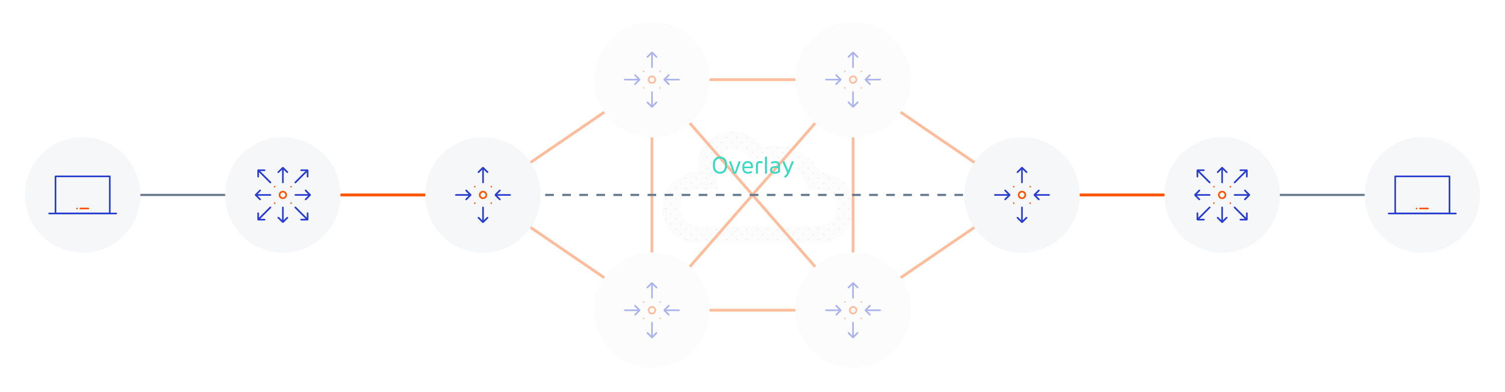
However from a logical standpoint, the following diagram shows the overlay network running on top of the underlay network. As you can see the logical topology has been greatly simplified.
The overlay in this example could support any of the following protocols it doesn’t just have to be LISP with VXLAN encapsulation (which are specific to Cisco’s implementation of SD-Access);
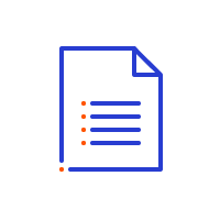
The control plane for LISP is effectively the equivalent of DNS, where an end host location is registered to a mapping server, and a lookup is performed against the mapping server to find the associated router when a host wants to communicate with it. The mapping server role can be colocated with a data plane LISP router but for scalability, it doesn’t have to be.
There are multiple roles and terminologies for devices that participate in LISP, they are summarised below:
Download our White Paper to gain insight into the features and functions of Intent Based Campus Fabrics with Software Defined Access.
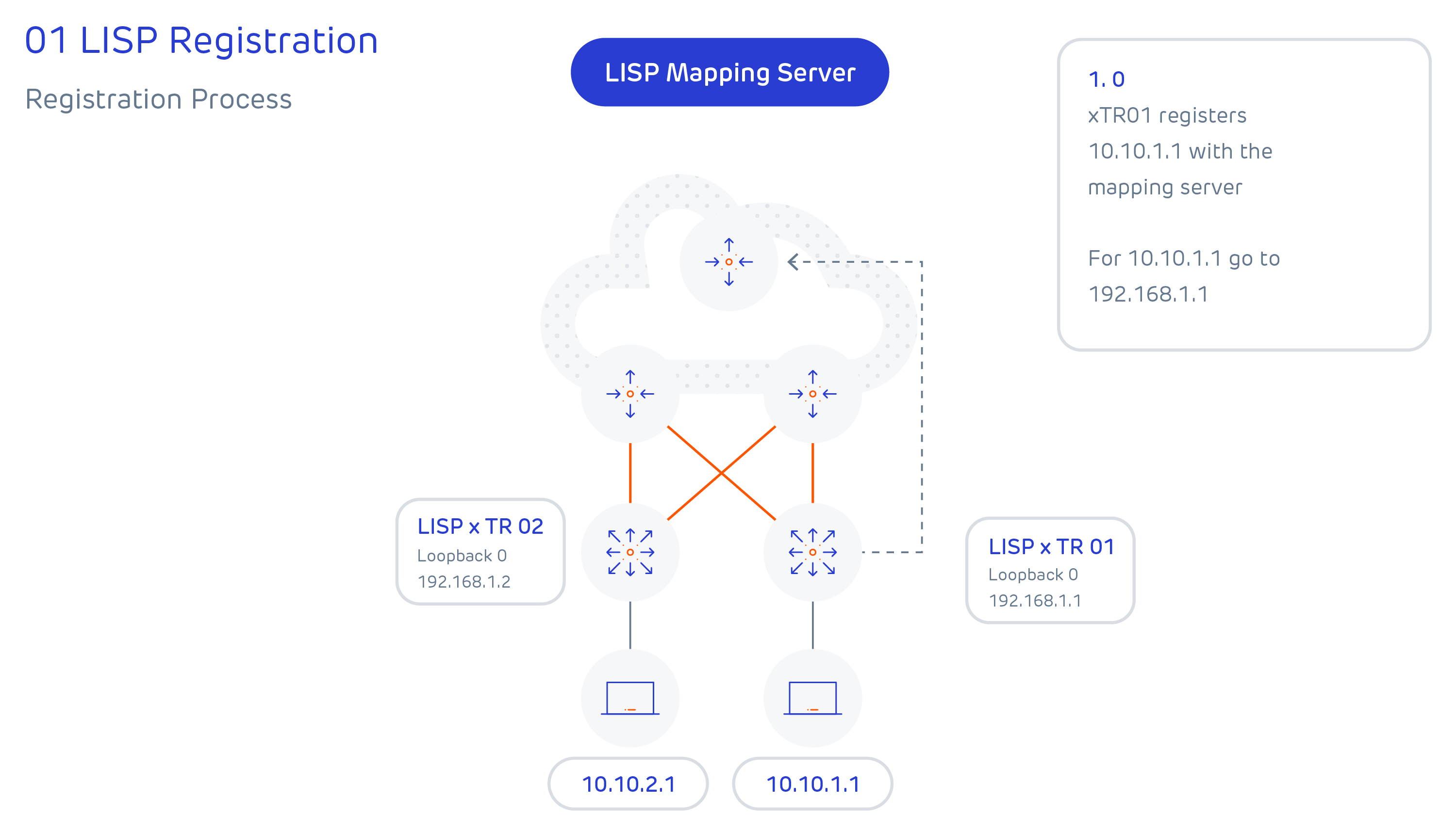
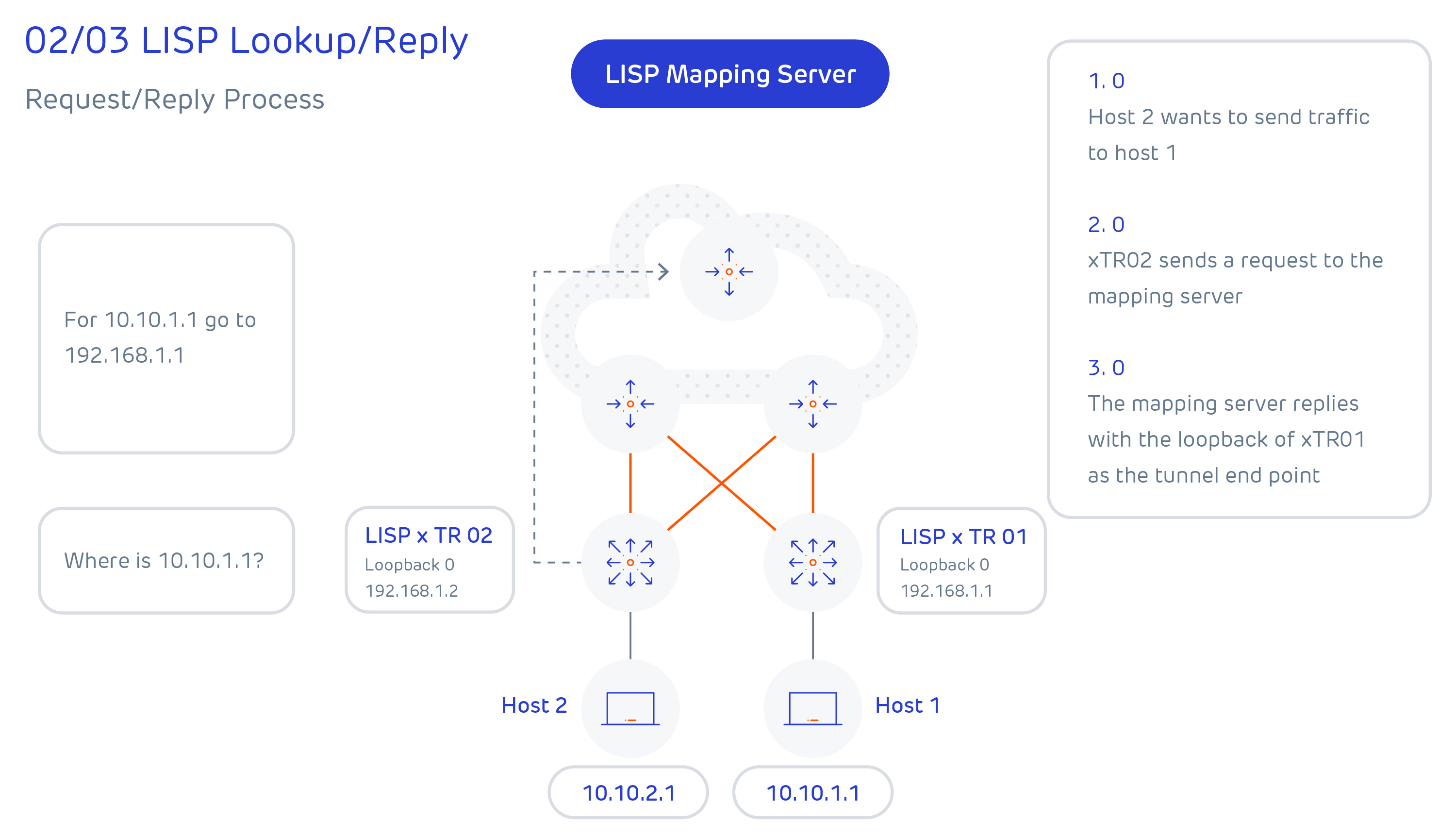
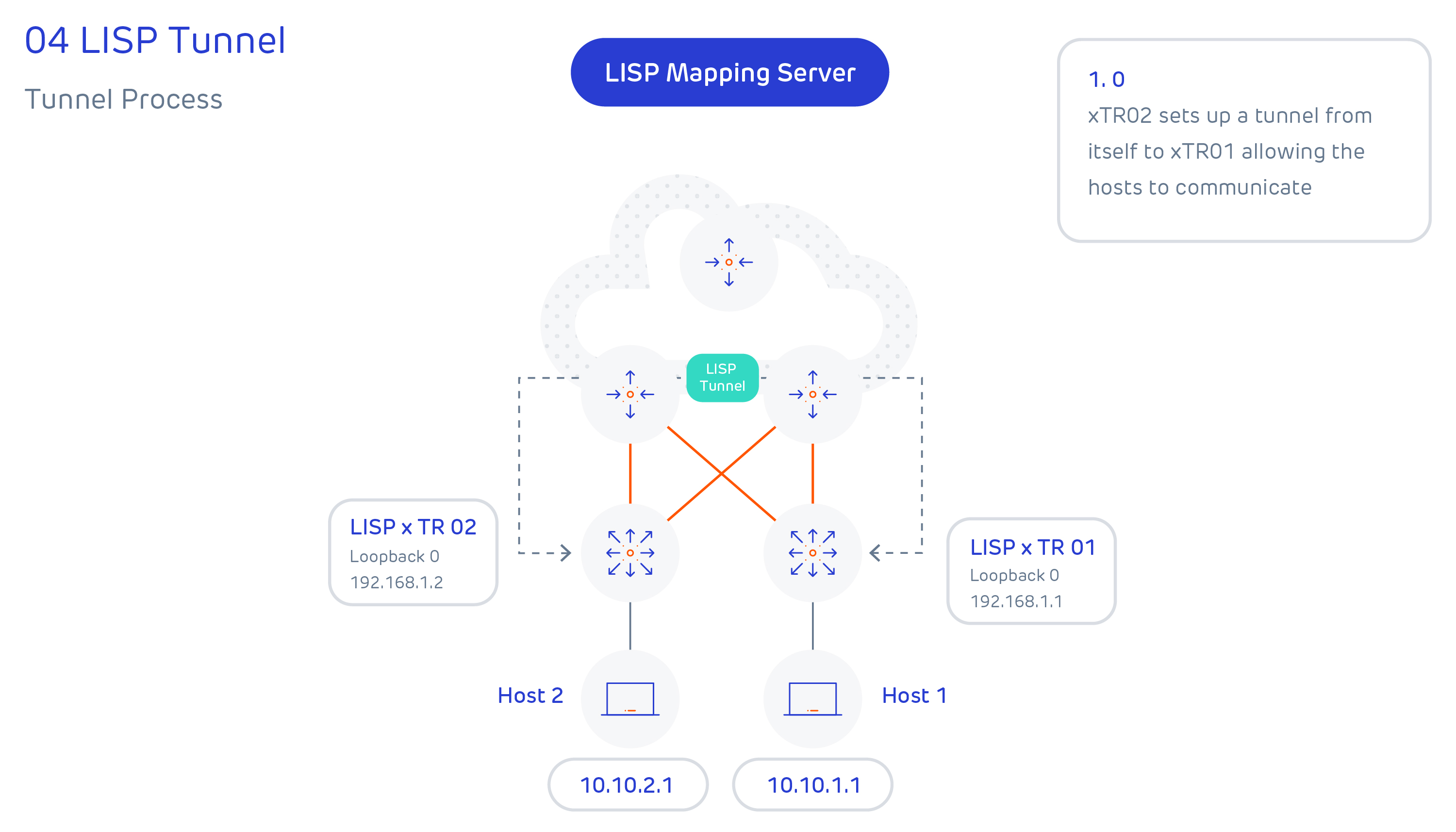
There are effectively 4-steps to LISP tunnel creation, and these are summarised below:
Book your free one-to-one
Compare SDN to traditional networks to discover whether it's right for your business with our Cisco Certified Internetwork Expert, Adrian Skinner.
